Honda B/D/H/F Series Coil-on-Plug Wiring Diagram
- 4 minutes read - 851 wordsIn this guide, I’ll show you the universal wiring diagram for converting any Honda B, D, H, or F series engine to coil-on-plug using Honda D17 or K-series coils. In the accompanying video, I’m doing this conversion on a 2001 Honda CR-V with a B20z engine, but this same wiring applies to all Honda B, D, H, and F series engines since they all use the same distributor harness setup.
Watch the Video
About This Conversion
This wiring diagram is universal for all Honda B, D, H, and F series engines because they all use the same distributor harness configuration. Whether you’re working on a B16, B18, B20, D16, H22, or F20/F22, the wiring is identical.
This conversion uses D17 or K-series coils, which are 3-wire coils that require:
- Switched ignition 12V (powers the coil)
- Constant ground (completes the circuit)
- Switched signal from the ECU (triggers spark timing)
The beauty of this setup is that it eliminates the mechanical distributor and gives your ECU precise control over ignition timing - critical for turbocharged applications or high-performance tuning.
In the video: I’m installing this on a 2001 Honda CR-V with a B20z engine, which is one of the most common swaps people do, but again - this exact wiring works for any B/D/H/F series Honda engine.
Wiring Diagram

Coil Pin Layout
Each coil has three pins in this order (left to right):
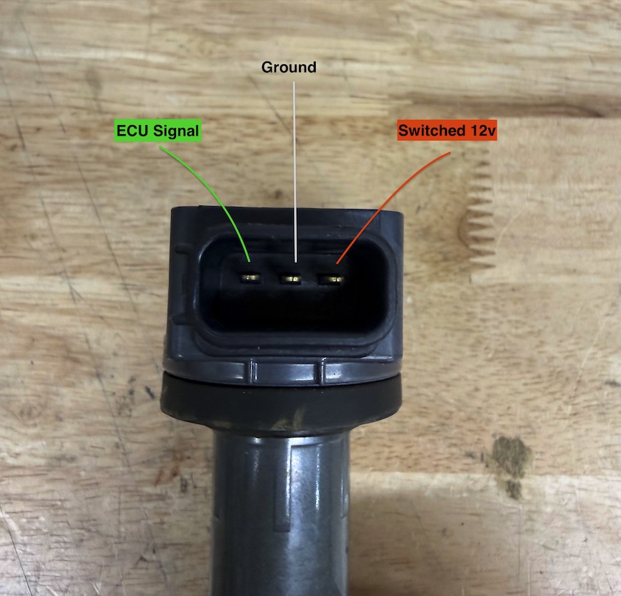
- Left pin: Signal (green wire to ECU)
- Middle pin: Ground (black wire to cylinder head)
- Right pin: Power (red wire to distributor harness)
Wiring Details
Power Supply (Switched Ignition 12V)
The switched ignition power comes from the black/yellow wire on the distributor harness. This is the same wire that used to power the distributor’s internal coil. You’ll tap into this wire to provide 12V power to all four coils.
Each coil receives power when the ignition is in the “on” position, but they only fire when the ECU grounds the signal wire.
Ground Connection
All four coils share a common ground that connects to a bolt on the cylinder head. This provides a solid, reliable ground path for the ignition system. Make sure to use a clean, paint-free surface on the cylinder head for the best connection.
ECU Signal Wires (Switched Ground)
The ECU controls each coil individually through four separate signal wires. These wires provide a ground path when the ECU wants that specific cylinder to fire. The ECU uses the crank and cam position sensors to determine the precise timing for each cylinder.
The four signal wires run from your coil-on-plug harness back through the firewall to the ECU. If you’re using an OBD1 ECU with a coil-on-plug daughter board (like the one from AE Race), these will plug directly into the daughter board.
Wire Colors (Typical Setup)
Note: Wire colors may vary depending on your harness manufacturer. Always verify with your specific harness documentation.
- Power (to all 4 coils): Taps into Black/Yellow from distributor harness
- Ground (from all 4 coils): Single wire to cylinder head bolt
- ECU Signals (4 individual wires): Connect to coil-on-plug ECU pins
- Cylinder 1 (shortest wire, passenger side)
- Cylinder 2
- Cylinder 3
- Cylinder 4 (longest wire, driver side)
Parts Needed for Wiring
- 4x Honda coil packs - D17 coils for non-VTEC B-series (D17 coils), K-series for VTEC B-series (K-series)
- Wire and connectors - Use the diagram above to make your own harness
- ECU with coil-on-plug capability - We’re using a Link ECU in the video from AE Race
Watch the full video for complete parts list and installation details.
Installation Tips
Route wires carefully: Keep all wiring away from hot exhaust components and moving parts like belts and throttle cables.
Wire length indicates cylinder: The harness wires are different lengths to reach each coil. Start with the shortest wire on cylinder 1 (passenger side) and work your way across.
Distributor stays in place: You still need the distributor for its crank/cam position sensors, but you can remove the internal coil and rotor. Consider using a distributor delete plate for a cleaner look.
Double-check your connections: The most critical connections are:
- Red/Power wire → Black/Yellow on distributor harness
- Ground wire → Clean bolt on cylinder head
- Signal wires → Correct pins on ECU daughter board
Test before final assembly: Before buttoning everything up, crank the engine and verify you have spark on all four cylinders.
Why Coil-on-Plug?
Upgrading to coil-on-plug offers several advantages:
- Better spark energy: Each cylinder gets its own dedicated coil
- Precise timing control: ECU can control timing individually per cylinder
- Improved tuning: Essential for turbocharged or high-compression builds
- No spark plug wires: Eliminates potential for plug wire failures
- Cleaner engine bay: No bulky distributor cap and wires
That’s it! Three wires per coil - power, ground, and signal. Whether you’re working on a B, D, H, or F series, the wiring is exactly the same. The hardest part is usually just routing everything cleanly away from hot exhaust parts.
If you’re planning a turbo build or just want more precise ignition control, coil-on-plug is definitely worth doing. Questions? Leave a comment on the video or hit me up on Instagram @joelatwar.